Overview
What is CNI?

CNI (Container Network Interface), a Cloud Native Computing Foundation project, consists of a specification and libraries for writing plugins to configure network interfaces in Linux containers, along with a number of supported plugins. CNI concerns itself only with network connectivity of containers and removing allocated resources when the container is deleted. Because of this focus, CNI has a wide range of support and the specification is simple to implement.
The Kubernetes network model
- Every Pod in a cluster gets its own unique cluster-wide IP address.
- Kubernetes imposes the following fundamental requirements on any networking implementation
- pods can communicate with all other pods on any other node without NAT
- agents on a node (e.g. system daemons, kubelet) can communicate with all pods on that node
Requirements for our CNI
- Kubernetes network model
- Security groups for pods
GKE
https://medium.com/cloudzone/gke-networking-options-explained-demonstrated-5c0253415eba
GKE currently supports two network modes: routes-based and VPC-native. The network mode defines how traffic is routed:
- between Kubernetes pods within the same node,
- between nodes of the same cluster
- other network-enabled resources on the same VPC, such as virtual machines (VMs).
Routes-Based Network Mode

- node has a single IP address from the subnet it is launched on (10.128.0.0/20)
- pod will also get an IP, however, is not registered in the VPC itself
- each node reserves a /24 IP address range that is unique within the VPC and not in use by any subnet (10.0.1.0/24, 10.0.2.0/24, ... ~ 254 IP/node)
- GKE then automatically creates a new route, using the node assigned /24 as the destination IP range and the node instance as the next hop.
- traffic between pods on different nodes is routed through the node’s IP address
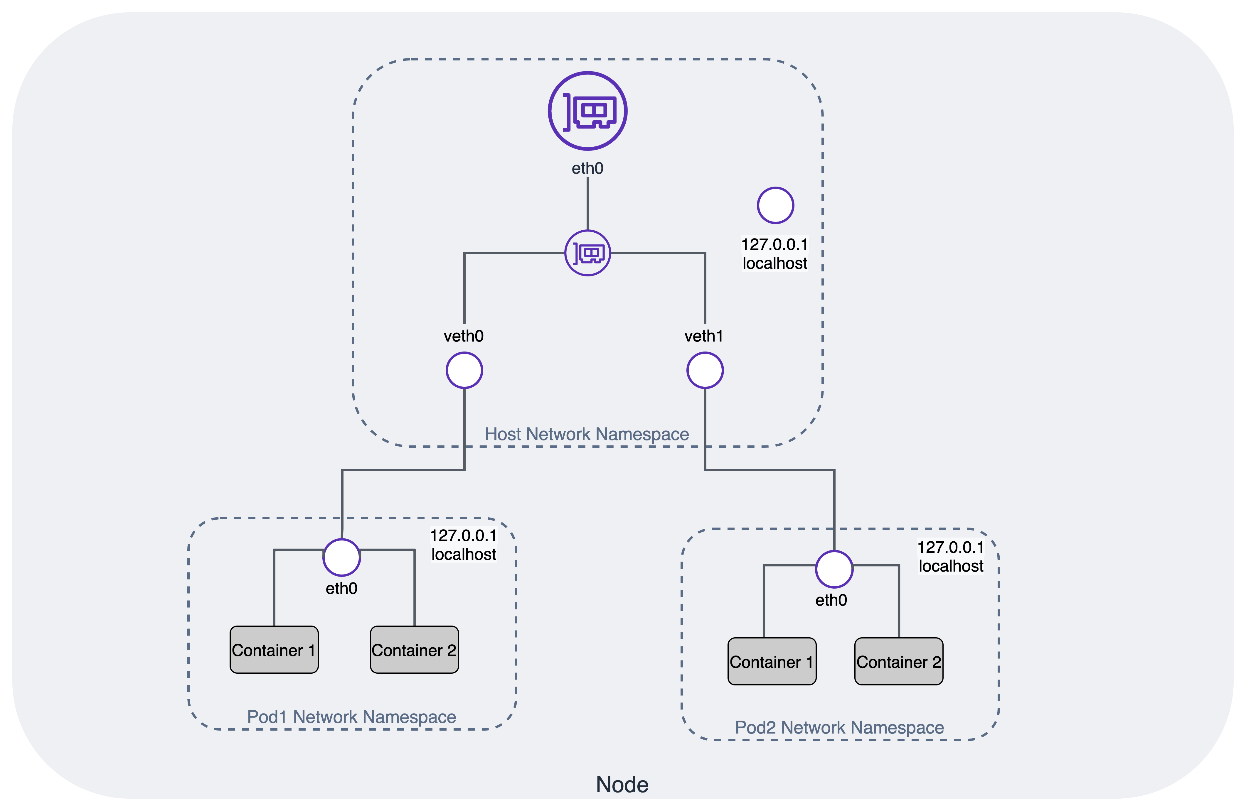
Networking inside a single GKE Node

- each pod has a fully isolated network from the node it runs on, using Linux network namespaces
- node connects to each of these eth0 interfaces on the pods using a virtual Ethernet (veth) device, which is always created as a pair between two network namespaces
- all veth interfaces on the node are connected together using a Layer 2 software-defined bridge cbr0
VPC-Native Network Mode
- This network mode uses a nifty feature called alias IP ranges
- it is possible to have an IP range assigned to the same network interface
- These addresses can then be assigned to applications or containers running inside the VM without requiring additional network interfaces.
- it is possible to add one or more secondary CIDR ranges to a subnet and use subsets of them as alias IP ranges.
- uses separate secondary address ranges for pods and Kubernetes services
- Alias IP ranges
- Google Cloud alias IP ranges let you assign ranges of internal IP addresses as aliases to a virtual machine's (VM) network interfaces
- useful if you have multiple services running on a VM and you want to assign each service a different IP address. Alias IP ranges also work with GKE Pods.
- You can also allocate alias IP ranges from that primary range, or you can add a secondary range to the subnet and allocate alias IP ranges from secondary range

- Each Node still reserves necessary IP range for ~ 110 pods per node, a /24 is required. But smaller is ok
- inside of a node — it is precisely the same as for clusters using the routes-based network mode
- no need to use the custom static routes created for each GKE Node
While this seems like a small difference between the two modes, it is highly advantageous.
-
Pod IP addresses are natively routable within the cluster's VPC network and other VPC networks connected to it by VPC Network Peering.
-
Pod IP addresses are reserved in the VPC network before the Pods are created in your cluster. This prevents conflict with other resources in the VPC network and allows you to better plan IP address allocations.
-
Pod IP address ranges do not depend on custom static routes. They do not consume the system-generated and custom static routes quota. Instead, automatically-generated subnet routes handle routing for VPC-native clusters.
-
You can create firewall rules that apply to just Pod IP address ranges instead of any IP address on the cluster's nodes.
-
Pod IP address ranges, and subnet secondary IP address ranges in general, are accessible from on-premises networks connected with Cloud VPN or Cloud Interconnect using Cloud Routers.
-
Some features, such as network endpoint groups (NEGs), only work with VPC-native clusters.
-
no drawbacks to choosing a VPC-native cluster
-
firewall rules can be applied to individual pods (for routes-based clusters, the finest granularity level would have been an entire node)
-
Service (ClusterIP) addresses are only available from within the cluster. If you need to access within the cluster's VPC, create an internal Network Load Balancer.
AWS EKS
Amazon VPC Container Network Interface(VPC CNI)
-
allows Kubernetes Pods to have the same IP address as they do on the VPC network
-
all containers inside the Pod share a network namespace, and they can communicate with each-other using local ports.
-
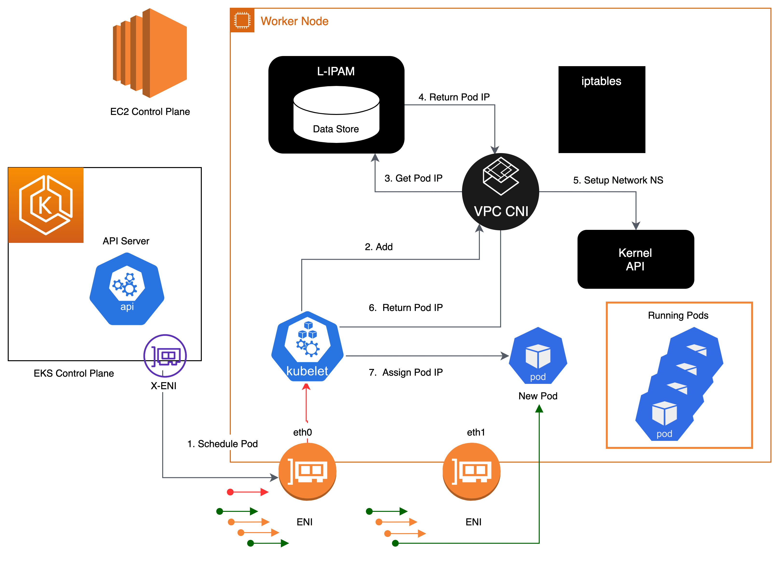
has two components
- CNI Binary, which will setup Pod network to enable Pod-to-Pod communication. The CNI binary runs on a node root file system and is invoked by the kubelet when a new Pod gets added to, or an existing Pod removed from the node.
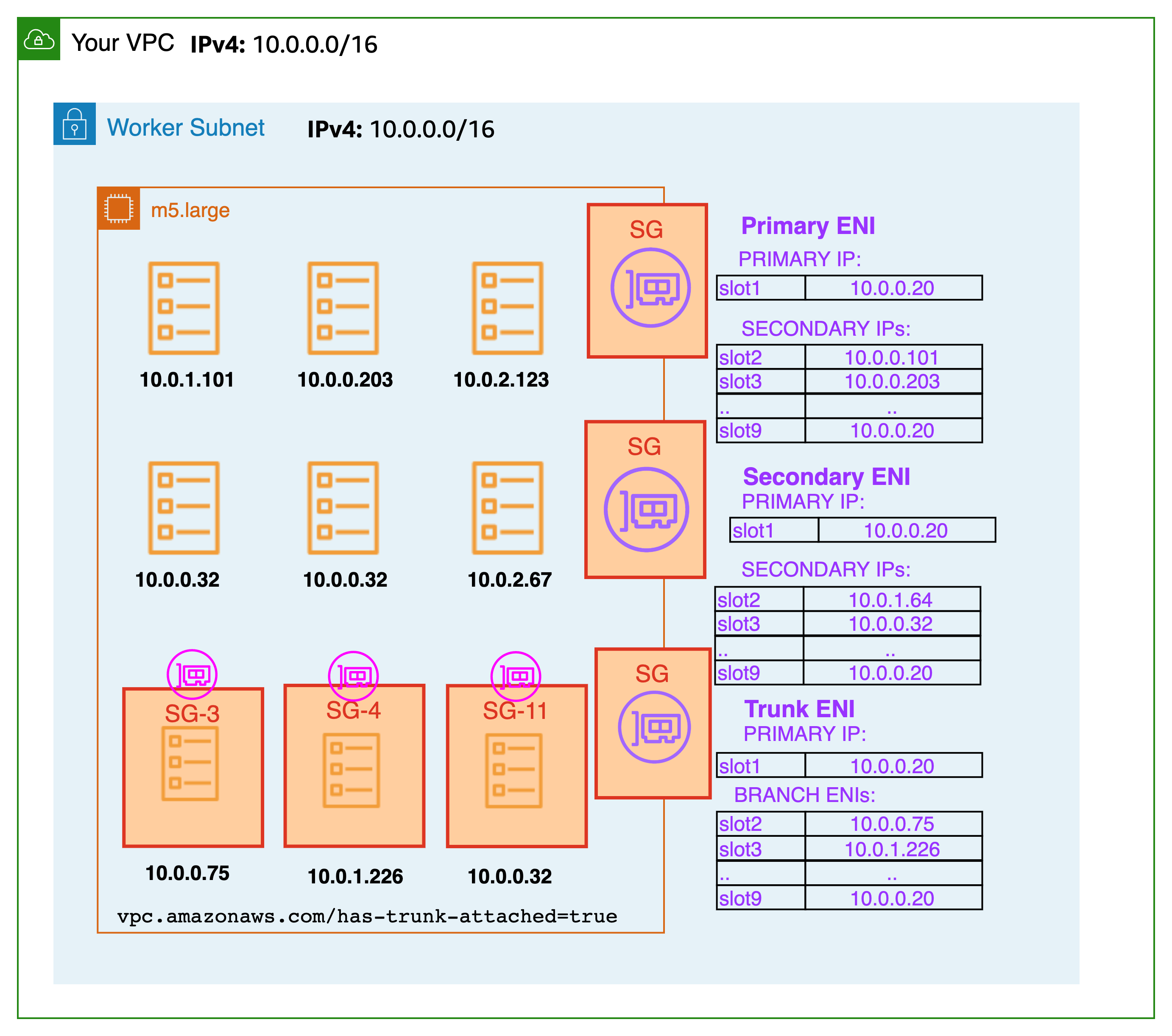
- ipamd, a long-running node-local IP Address Management (IPAM) daemon and is responsible
- managing ENIs on a node
- maintaining a warm-pool of available IP addresses or prefix
-
When an instance is created, EC2 creates and attaches a primary ENI associated with a primary subnet. The Pods that run in hostNetwork mode use the primary IP address assigned to the node primary ENI and share the same network namespace as the host.
2024-06-25
Next-step
-
benefit of secgroup, requirement, how to apply
-
Network policy
-
policy based routing when set
ip rule-
it's controls the route selection algorithm
-
Classic, routing algorithms only on the destination address of packets
-
In some circumstances, we want to route packets on other packet fields: source address, IP protocol, transport protocol, ports or even packet payload. This task is called
policy routing. -
use
routing policy database(RPDB) to solve -
in aws
10: from all iif vlan.eth.3 lookup 103
10: from all iif vlan14d01641e41 lookup 103
20: from all lookup local
512: from all to 172.31.28.221 lookup main
512: from all to 172.31.24.86 lookup main
512: from all to 172.31.18.117 lookup main
1024: from all fwmark 0x80/0x80 lookup main
32766: from all lookup main
32767: from all lookup default
-
-
benchmark performance of (calico+kube_proxy+iptables) vs (calico+kube_proxy+ipvs) vs (cilium+ebpf)
-
why config default gateway
169.254.1.1in network namespace and static ARP- Address Resolution Protocol (ARP) is a protocol used to map IP addresses to MAC addresses. ARP is used to determine the MAC address of a device on the same network.
- ARP table is not have entry for the default gateway, so the packet will be
Destination Host Unreachable - Instead, use a default gateway IP address, config a static ARP entry for the default gateway IP address.
Benefit of secgroup
GKE firewall rule
-
VPC network
-
priority
-
direct traffic (ingress/egress)
-
Action on match: allow/deny
-
target
- all instances in the network
- tags
- service account
-
source filter
- IP range v4 v6
- service account
- tag
- SA
-
destination filter
- IP range v4 v6
- none
-
Apply for Protocols and ports (TCP, UDP, ...)
-
tao service account tranh dynamic IP ???
EKS
Configure Security groups for Pods link
-
Enable Pod CNI:
ENABLE_POD_ENI=true -
Create SecurityGroupPolicy CRD
apiVersion: vpcresources.k8s.aws/v1beta1 kind: SecurityGroupPolicy metadata: name: my-security-group-policy namespace: my-namespace spec: podSelector: matchLabels: role: my-role # -----> Pod Label Selector securityGroups: groupIds: - my_pod_security_group_id # -----> Security Group ID -
Apply for Pods
apiVersion: apps/v1
kind: Deployment
metadata:
  name: my-deployment
  namespace: my-namespace
  labels:
    app: my-app
spec:
  replicas: 4
  selector:
    matchLabels:
      app: my-app
  template:
    metadata:
      labels:
        app: my-app
        role: my-role # -----> Pod Label Selector
    spec:
      terminationGracePeriodSeconds: 120
      containers:
      - name: nginx
        image: public.ecr.aws/nginx/nginx:1.23
        ports:
        - containerPort: 80
How it works ?
- It requires each Pod to have a unique security group => each Pod has a unique ENI
- Inside node:
# ip a
1: lo: <LOOPBACK,UP,LOWER_UP> mtu 65536 qdisc noqueue state UNKNOWN group default qlen 1000
    link/loopback 00:00:00:00:00:00 brd 00:00:00:00:00:00
2: eth0: <BROADCAST,MULTICAST,UP,LOWER_UP> mtu 9001 qdisc mq state UP group default qlen 1000 # <--- node ENI
    link/ether 0a:47:ee:98:ee:5f brd ff:ff:ff:ff:ff:ff
3: dummy0: <BROADCAST,NOARP> mtu 1500 qdisc noop state DOWN group default qlen 1000
    link/ether 0e:f3:c5:05:4d:65 brd ff:ff:ff:ff:ff:ff
4: pod-id-link0: <BROADCAST,NOARP,UP,LOWER_UP> mtu 1500 qdisc noqueue state UNKNOWN group default qlen 1000
    link/ether fa:5a:38:0b:67:8c brd ff:ff:ff:ff:ff:ff
5: eni4c9bab731ed@if3: <BROADCAST,MULTICAST,UP,LOWER_UP> mtu 9001 qdisc noqueue state UP group default
    link/ether 3a:c7:2c:0d:ca:0f brd ff:ff:ff:ff:ff:ff link-netns cni-da53182a-dd25-596a-fae3-2d0556c2692a
6: eth1: <BROADCAST,MULTICAST,UP,LOWER_UP> mtu 9001 qdisc mq state UP group default qlen 1000 # <--- trunk ENI
    link/ether 0a:af:27:4c:70:db brd ff:ff:ff:ff:ff:ff
7: eth2: <BROADCAST,MULTICAST,UP,LOWER_UP> mtu 9001 qdisc mq state UP group default qlen 1000
    link/ether 0a:66:21:94:e5:f1 brd ff:ff:ff:ff:ff:ff
8: eni2bc5393b053@if3: <BROADCAST,MULTICAST,UP,LOWER_UP> mtu 9001 qdisc noqueue state UP group default
    link/ether 96:cb:92:f3:47:53 brd ff:ff:ff:ff:ff:ff link-netns cni-55ae0531-a760-9e14-a192-fdc6d6c82970
11: vlan14d01641e41@if3: <BROADCAST,MULTICAST,UP,LOWER_UP> mtu 9001 qdisc noqueue state UP group default # <--- pod ENI
    link/ether a2:bc:f2:84:d3:26 brd ff:ff:ff:ff:ff:ff link-netns cni-b3466bf5-4367-e10f-09dd-99abc561194e
12: vlan.eth.3@eth1: <BROADCAST,MULTICAST,UP,LOWER_UP> mtu 9001 qdisc noqueue state UP group default qlen 1000 # <--- VLAN pod ENI
    link/ether 0a:c0:2c:46:6f:33 brd ff:ff:ff:ff:ff:ff
17: eni37cc5983ec1@if3: <BROADCAST,MULTICAST,UP,LOWER_UP> mtu 9001 qdisc noqueue state UP group default
    link/ether 1e:6e:56:e4:a5:25 brd ff:ff:ff:ff:ff:ff link-netns cni-29b37092-bcad-2228-1130-8b9945f6bb30

# ip netns
cni-29b37092-bcad-2228-1130-8b9945f6bb30 (id: 6)
cni-b3466bf5-4367-e10f-09dd-99abc561194e (id: 3) # <--- pod have security group
cni-55ae0531-a760-9e14-a192-fdc6d6c82970 (id: 1)
cni-da53182a-dd25-596a-fae3-2d0556c2692a (id: 0)

# ip route # No route for pod ENI
default via 172.31.16.1 dev eth0
169.254.169.254 dev eth0
169.254.170.23 dev pod-id-link0
172.31.16.0/20 dev eth0 proto kernel scope link src 172.31.17.137
172.31.18.117 dev eni37cc5983ec1 scope link
172.31.24.86 dev eni2bc5393b053 scope link
172.31.28.221 dev eni4c9bab731ed scope link
| Multi port - multi NIC - multi interface | multi port - trunk port |
|---|---|
 | 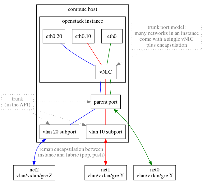 |
Network policy
Benchmark performance
- protocol: TCP
- Step:
- [prepare] Deployment of nodes, installation of Kubernetes, and CNI setup
- [info] Information gathering, such as collecting MTU data of interfaces
- [idle] Idle performance measurement to gauge the CPU and memory overhead post-CNI installation
- [dts] Direct pod-to-pod TCP bandwidth with a Single stream
- [dtm] Direct pod-to-pod TCP bandwidth with Multiple streams (8)
- [dus] Direct pod-to-pod UDP bandwidth with a Single stream
- [dum] Direct pod-to-pod UDP bandwidth with Multiple streams (8)
- [sts] Pod to Service TCP bandwidth with a Single stream
- [stm] Pod to Service TCP bandwidth with Multiple streams (8)
- [sus] Pod to Service UDP bandwidth with a Single stream
- [sum] Pod to Service UDP bandwidth with Multiple streams (8)
- [teardown] Deinstallation of all nodes and Kubernetes cluster